Network diagram

A network diagram shows the interconnections between entities. It is consituted by nodes that represent entities and by links that show relationships between entities.
This page is a step by step tutorial explaining how to build a network diagram component with React and D3.js. It relies on the d3-force plugin to compute the node positions. It comes with explanations and code sandboxes. It starts by simple concepts like how to format the data and how to draw nodes and links in SVG, and then goes further with hover effect, tooltip and more.
The Data
Two layers of information are required to build a network diagram: a list of nodes to build the circles and a list of links to build the lines.
Many different data structures can be used to store such information. In this tutorial I suggest to start with the following:
export const data = {
  nodes: [
      { id: "Myriel", group: 'team1' },
      { id: "Anne", group: 'team1' },
      ...
  ],
  links: [
      { source: "Anne", target: "Myriel", value: 1 },
      { source: "Napoleon", target: "Myriel", value: 1 },
      ...
  ]
}
data is an object with 2 properties: nodes and links.
nodesis an array where each node is an object defined by itsidand itsgroup. Note that any other feature can be added to nodes here.linksis another array listing the connections. They are defined by asourceand atargetand optionnaly with avalue. Note that allsourceandtargetvalues must have a value in thenodesarray.
ToDoExplain how to build this data structure from various initial formats
Component skeleton
The goal here is to create a NetworkDiagram component that will be stored in a NetworkDiagram.tsx file. This component requires 3 props to render: a width, a height and some data.
The shape of the data is described above. The width and height will be used to render an svg element in the DOM, in which we will insert the arc diagram.
To put it in a nutshell, that's the skeleton of our NetworkDiagram component:
import * as d3 from "d3"; // we will need d3.js

type NetworkDiagramProps = {
  width: number;
  height: number;
  data: number[];
};

export const NetworkDiagram = ({ width, height, data }: NetworkDiagramProps) => {

  // read the data
  // compute the nodes position using a d3-force
  // build the links
  // build the nodes

  return (
    <div>
      <svg width={width} height={height}>
        // render all the lines and circles
      </svg>
    </div>
  );
};
It's fundamental to understand that with this code organization, d3.js will be used to prepare the SVG circle and lines, but it's React that will render them in the return() statement. We won't use d3 methods like append that you can find in usual d3.js examples.
Compute node positions with d3-force
The hardest part of a network diagram construction is to compute the node positions. Fortunately, the d3-force plugin allows to simulate physical forces on our nodes to find insightful layouts.
d3-force docEverything is done thanks to the forceSimulation() function. This function expects an array of nodes as described in the data section above.
it also expects a list of forces to apply to the nodes. Many kind of physical forces are offered and will be described more in depth later in this post.
To put it in a nutshell, here is an example of a call to theforceSimulation function
d3.forceSimulation(nodes) // apply the simulation to our array of nodes

  // Force #1: links between nodes
  .force( 'link', d3.forceLink(links).id((d) => d.id))

  // Force #2: avoid node overlaps
  .force('collide', d3.forceCollide().radius(RADIUS))

  // Force #3: attraction or repulsion between nodes
  .force('charge', d3.forceManyBody())

  // Force #4: nodes are attracted by the center of the chart area
  .force('center', d3.forceCenter(width / 2, height / 2));
This function is going to run a simulation. It is a basically a loop. At each iteration the function tries to improve the node positions until it is satisfied by the result.
The input we provide to the function (the array of nodes) is progressively mutated. Some very useful properties are added to it! x and y for instance are now providing the node position on the 2d coordinate system 🎉.
This is how nodes is now looking like:
// Mutated nodes once the simulation has been run
[
  { id: "Myriel", group: 'team1', x: 200, y: 34.5, index: 0, ... },
  { id: "Anne", group: 'team1', x: 100, y: 53.2, index: 1, ... },
  ...
],
Note that pretty much the same thing happens to the array of links. The array is mutated, now providing the source and target coordinates too.
This is it! Now it is just a matter of drawing those nodes and links with the available coordinates. 🔥
Render nodes and links using canvas
Rendering a network diagram is a bit more tricky than many other chart types described in this gallery:
→ Simulation takes time
Running the simulations with forceSimulation() to get the node positions takes time. Even with a small dataset like below it takes a few seconds. Since we do not want to leave the graph area empty for such a long period of time, a common workaround is to update the node positions at each iteration of the simulation.
Fortunately this is possible using the on('tick', ...) method of forceSimulation(). Using the code below I can call a hand-made function called drawNetwork that will render the graph at each iteration.
.on('tick', () => {
  drawNetwork(context, width, height, nodes, links);
});
Note that the simulation is run in a useEffect hook. It allows to first initialize the graph area in the DOM, and then render the content into it.
→ Performance is key
The number of items to draw in the network diagram is often big. And we need to render it many times, at each iteration of the simulation. Adding that many SVG elements to the DOM could be very bad in term of performance.
This is why I strongly advise to use a canvas element to render the shapes. The drawNetwork() function could look as something like this:
export const RADIUS = 10;

export const drawNetwork = (context, width, height, nodes, links,) => {
  context.clearRect(0, 0, width, height);

  // Draw the links first
  links.forEach((link) => {
    context.beginPath();
    context.moveTo(link.source.x, link.source.y);
    context.lineTo(link.target.x, link.target.y);
    context.stroke();
  });

  // Draw the nodes
  nodes.forEach((node) => {
    context.beginPath();
    context.moveTo(node.x + RADIUS, node.y);
    context.arc(node.x, node.y, RADIUS, 0, 2 * Math.PI);
    context.fillStyle = '#cb1dd1';
    context.fill();
  });
};
Using canvas instead of SVG is a very important concept when preformance needs to be improved in a data visualization. I am preparing a full post on the topic so feel free to subscribe to the project to know when it is ready!
More about CanvasHere is a code sandbox putting all of this into action. It results in a first simple network diagram. Refresh the page to see the simulation running and the node slowly reaching their final positons.
A first network diagram built using react and d3-force.
Responsive Network with react
The component above is not responsive. It expects 2 props called width and height and will render a Network of those dimensions.
Making the Network responsive requires adding a wrapper component that gets the dimension of the parent div, and listening to a potential dimension change. This is possible thanks to a hook called useDimensions that will do the job for us.
useDimensions: a hook to make your viz responsive
export const useDimensions = (targetRef: React.RefObject<HTMLDivElement>) => {

  const getDimensions = () => {
    return {
      width: targetRef.current ? targetRef.current.offsetWidth : 0,
      height: targetRef.current ? targetRef.current.offsetHeight : 0
    };
  };

  const [dimensions, setDimensions] = useState(getDimensions);

  const handleResize = () => {
    setDimensions(getDimensions());
  };

  useEffect(() => {
    window.addEventListener("resize", handleResize);
    return () => window.removeEventListener("resize", handleResize);
  }, []);

  useLayoutEffect(() => {
    handleResize();
  }, []);

  return dimensions;
}
I'm in the process of writing a complete blog post on the topic. Subscribe to the project to know when it's ready.
Network inspiration
If you're looking for inspiration to create your next Network, note that dataviz-inspiration.com showcases many examples. Definitely the best place to get ... inspiration!
dataviz-inspiration.com showcases hundreds of stunning dataviz projects. Have a look to get some ideas on how to make your Network looks good!
visitAvailable forces
The exausthive list of forces that can be applied to nodes is available in the official documentation. Here is an overview of the main ones:
d3.forceManyBody()→ simulates attraction between nodes if its strength is positive, repulsion otherwise.d3.forceCenter()→ translates nodes uniformly so that the mean position of all nodes is at a given position.d3.forceCollide()→ tries to avoid node collision and overlap. You can provide aradiusand astrength.d3.forceLink()→ pushes linked nodes together or apart according to the desired link distance.d3.forceX()→ applies a force toward a X position to all nodes.d3.forceY()is also available.
A first network diagram built using react and d3-force.
Variations
Once you've understood how to build a basic network diagram with d3 and react, it opens an infinite world of customization. Here are a few examples using the same concepts.
Click on the overview below to get details and code.
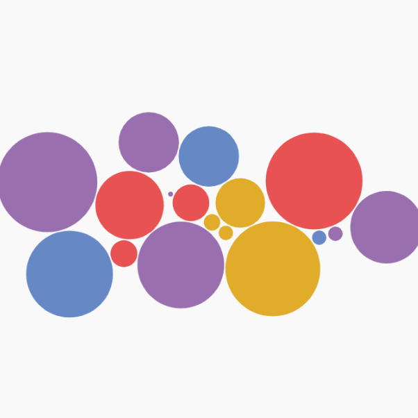
Circle Pack with d3-force
Another approach to build a circle packing chart using physical forces to compute node positions.
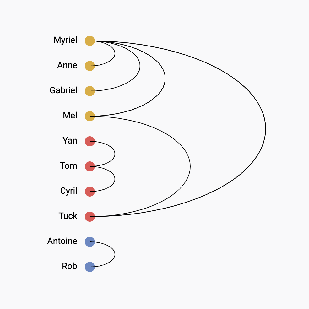
Vertical arc diagram
The vertical version of the arc diagram is more convenient to display labels
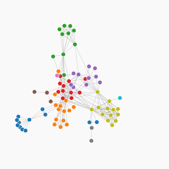
Force directed graph
A force directed network chart showing character co-occurence in les miserables


Contact
👋 Hey, I'm Yan and I'm currently working on this project!
Feedback is welcome ❤️. You can fill an issue on Github, drop me a message on LinkedIn, or even send me an email pasting yan.holtz.data with gmail.com. You can also subscribe to the newsletter to know when I publish more content!
